 Hi Boox Popular Magazine 2024
If you are eager to understand how your machine works and what couplings are used for, keep reading. We will explain the basic characteristics that will help you get a better idea about the functionality of each one. These are devices that enable the proper work of a machine. When you want to join shafts together you need a coupling. Its purpose is transmitting power. It can provide 2 types of connections: flexible and rigid. Usually, the disconnection of shafts while the operation is in progress is not allowed. However, there are certain types that can, in fact, enable disconnection in certain situations. Also, their purpose is to absorb vibration and shock.
The factors that impact the choice of couplings
Since there are various couplings, it is important to determine the condition of the misalignment or the movement of the shafts. In cases when the pivot hub is not similar to the shafts, we have a parallel misalignment. The other factor is when the edge is not balanced or symmetrical on the place where they are not aligned. There is also the case of angular misfitting where there are no coaxial movements or parallel movement. In case when there is a pivotal movement of any of the shafts, we have end drift. The last one is the so-called torsional adaptability which is usually caused by vibration or shock.
Types of couplings
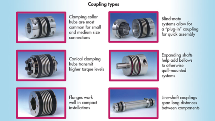
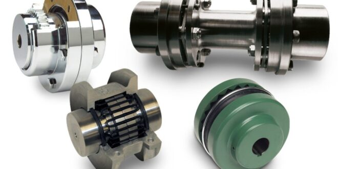
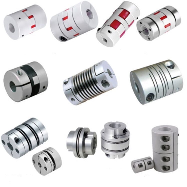
There are various types of couplings and we will describe each one, so you can get a better idea of their applications as well.
- Rigid couplings are the ones where shafts are locked with flange. Their main use is in cases when the shafts are fully aligned. They are bolted so they can be rigid with zero tolerance for axial, angular or radial movement of the shafts. In case there is no true alignment, there is a very high probability of failure. There is no flexibility in this type of coupling. When it comes to rigid coupling, there are clamper, flanged, and sleeve couplings.
- Muff coupling resembles a hollow pipe or a cylinder which is why they are also called sleeve couplings. Manufacturing of the sleeve is done with the shaft diameter in mind with the goal of a perfect fit. There are also a few threaded holes to prevent movements when the bolts are used. Everything is designed in such a way that there is no possibility of slipping. The great thing about it is that it is pretty simple for manufacturing. They are used in cases when there is no need for alignment or in cases when the load capacity is either light or medium.
- Split muff coupling is very similar to the previous one with one different – it is split into two parts. Their shape is semi-cylindrical. The holes that can be seen on them can be jointed with studs or steel bolts. The great thing about them is that they can be easily assembled or disassembled while the shaft position remains unchanged. Their purpose is to be used in cases of medium to heavy load capacity.
- Flange coupling is pretty simple for manufacturing. There are numerous similarities to the sleeve coupling. Flanges can be seen on both sides of the sleeves and have an even number of threading holes. Joint flanges are done with nuts and bolts. A tapered key is used to ensure that there is no loosening up or moving in any direction. This type is used for medium or heavy load capacity.
- Bush pin coupling is an improved model of the flange coupling. The main thing that differentiates them is the rubber bushings usage. The greatest advantage of this type of coupling is that it can be easily used for shafts that are slightly misaligned. They add a certain percentage of flexibility which helps with absorbing vibrations and shock. These couplings are usually used for cases where there is an axial, parallel, or angular misalignment.
- A gear coupling is similar to flange coupling. The hub and the flange are assembled together and this is what makes it different from flange coupling. This type of coupling is used for heavy-duty applications.
- The fluid coupling is comprised of two parts: a turbine and a pump. There are also blades inside and they are placed at a certain angle. The pump is placed at the driver shaft end, while the driven shaft gets the turbine. When the fluid enters the pump, the rotation of the driver shaft occurs powered by the centrifugal force. When the reactor is added, it becomes a torque converter. Its main use is in industrial and marine applications.
- Rzeppa joint is known also as a constant velocity coupling or CV. With this type of coupling, the power gets transmitted varying angles. Grease gets added to protect the joint. This type of joint is used for independent rear suspension vehicles.
- The universal joint has a broad use and can be used in various cases. It is very practical and useful. Their main use is for the machines when the flexibility is necessary or when there are space restrictions. Also, it can find its use when there is a need for transmitting rotary motion.
These were basic descriptions of the main types of couplings that you are most likely to use. If you want to find out more about a specific one, click here. If you are not sure about the type of coupling you need and which solution would be the best, perhaps it is better to consult an expert who will be able to assess the situation based on the specific problem you have.
Each of these couplings has numerous benefits and uses, so it is necessary to have in-depth knowledge about each one if you have to prolong the life of your machine as much as possible. We hope we helped you shed a little light on this demanding topic and inspired you to keep learning.